ecoflow-comprehensive-guide
EcoFlow LFP Battery Adapter & Termination
This guide covers the teardown and pinout exploration of the EcoFlow LFP Battery Adapter and the proprietary communication protocols used to activate the battery.
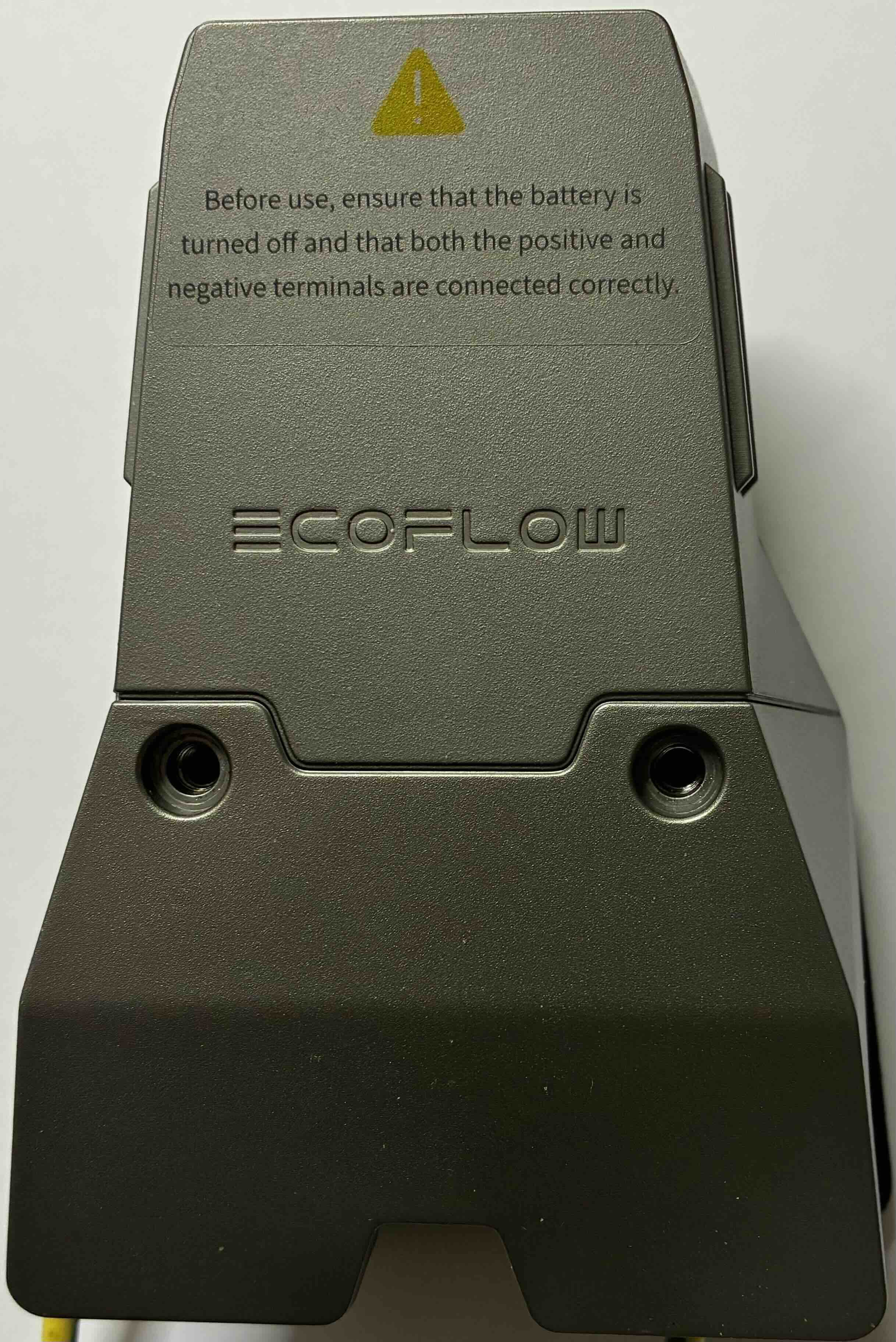
🔌 LFP Battery Adapter Overview
The EcoFlow LFP Battery Adapter is used to connect Delta Pro Extra Batteries (LFP) to third-party 48V/60V inverters or the EcoFlow Power Kits.
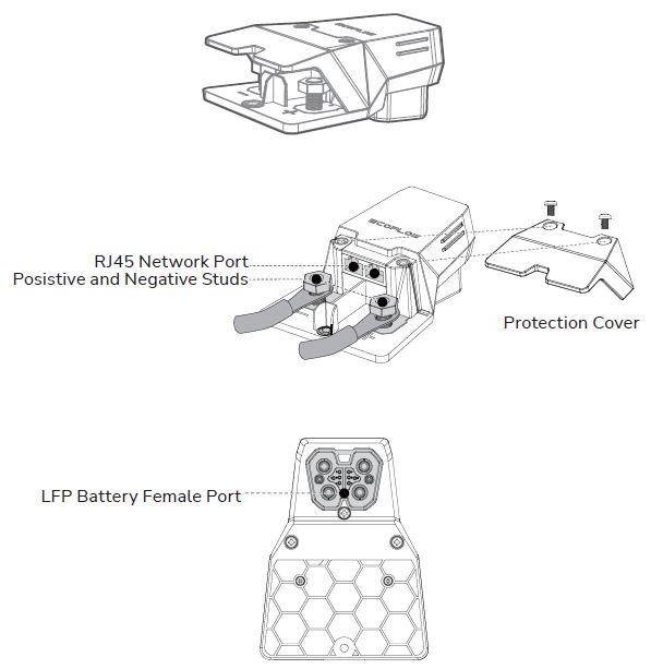 Official diagram showing RJ45 ports, power studs, and the LFP female battery port.
Activation logic
Normally, the battery terminal is “dead” (0V) until a handshake is performed via the communication pins.
According to community measurements and teardowns:
- Pins 4 and 5 on the communication interface are internally shorted within the adapter.
- By shorting Pin 4 and Pin 5, the BMS (Battery Management System) activates the main MOSFETs.
- Once pins 4 and 5 are bridged, the main terminals will output nominal voltage (approx. 51.2V - 58V depending on SoC).
[!WARNING] DANGER: Always use a fuse when bypassing safety checks. Shorting wrong pins can permanently damage the BMS or cause a fire.
🛠 Technical Pinout & Wiring
The adapter serves as a bridge between the battery’s proprietary signal interface and standard RJ45 CAN Bus ports.
Signal Connector (8-Pin)
Orientation: Tab at the top, pins numbered right to left (1 to 8).
| Pin | Mapping | Function |
|---|---|---|
| 1 | RJ45 Pins 1 | CAN Data Pair (See Terminator) |
| 2 | RJ45 Pins 2 | CAN Data Pair (See Terminator) |
| 3 | RJ45 Pins 7 | Signal / Ground ? |
| 4 | RJ45 Pins 4 | Bridge to Pin 5 (Activate Battery) |
| 5 | RJ45 Pins 4 | Bridge to Pin 4 (Activate Battery) |
| 6 | N/C | Not Connected |
| 7 | N/C | Not Connected |
| 8 | RJ45 Pins 5 & 8 | Signal / Ground ? |
RJ45 CAN Bus Ports
The adapter features two parallel RJ45 ports. These are used for daisy-chaining multiple batteries or connecting to the EcoFlow Power Kit Console/Wireless Dongle.
Internal Wiring (Adapter to RJ45):
- Adapter Pin 1 → RJ45 Port 1 (Pin 1) & RJ45 Port 2 (Pin 1)
- Adapter Pin 2 → RJ45 Port 1 (Pin 2) & RJ45 Port 2 (Pin 2)
- Adapter Pin 3 → RJ45 Port 1 (Pin 7) & RJ45 Port 2 (Pin 7)
- Adapter Pin 4 & 5 (Shorted) → RJ45 Port 1 (Pin 4) & RJ45 Port 2 (Pin 4)
- Adapter Pin 8 → RJ45 Port 1 (Pins 5 & 8) & RJ45 Port 2 (Pins 5 & 8)
🔌 CAN Bus Terminator
When bypassing the official ecosystem or daisy-chaining batteries, a terminator is required on any unused RJ45 port to prevent signal reflection.
Specifications:
- Resistor: 120 Ohm.
- Connection: Bridged between Pin 1 and Pin 2 of the RJ45 plug.
[!NOTE] Official EcoFlow documentation states: “When two or more battery packs are connected and the RJ45 CAN Bus port is not connected… a terminator MUST be connected to ensure proper communication.”
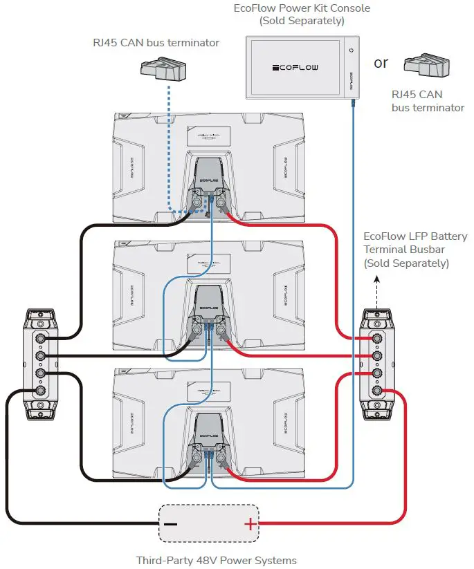 Official schematic for parallel connection of multiple batteries. Notice how the RJ45 chain forms a unified CAN bus across all units.
Manual Analysis:
- Daisy Chaining: The two RJ45 ports are strictly for CAN Bus continuity. Each battery in a parallel stack must “see” the same communication bus.
- Terminal Isolation: The diagram confirms that even in parallel, the communication bus is critical for the “Master” (or the console) to manage the state of charge across all packs.
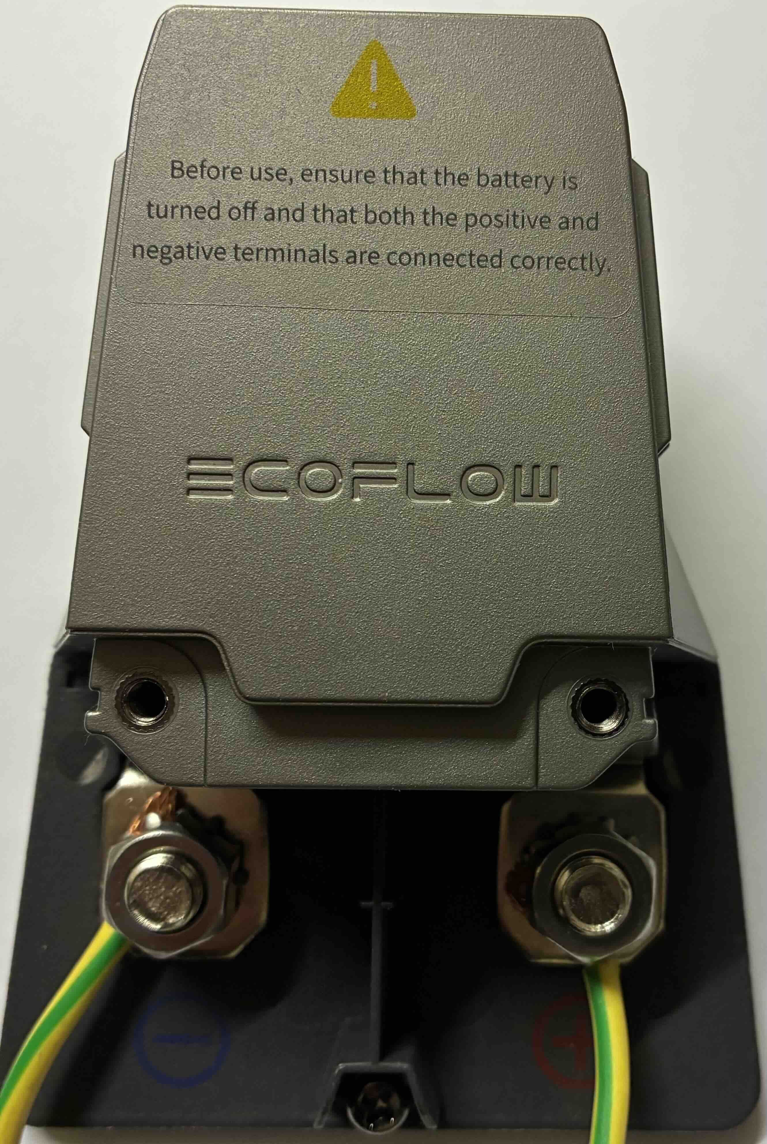
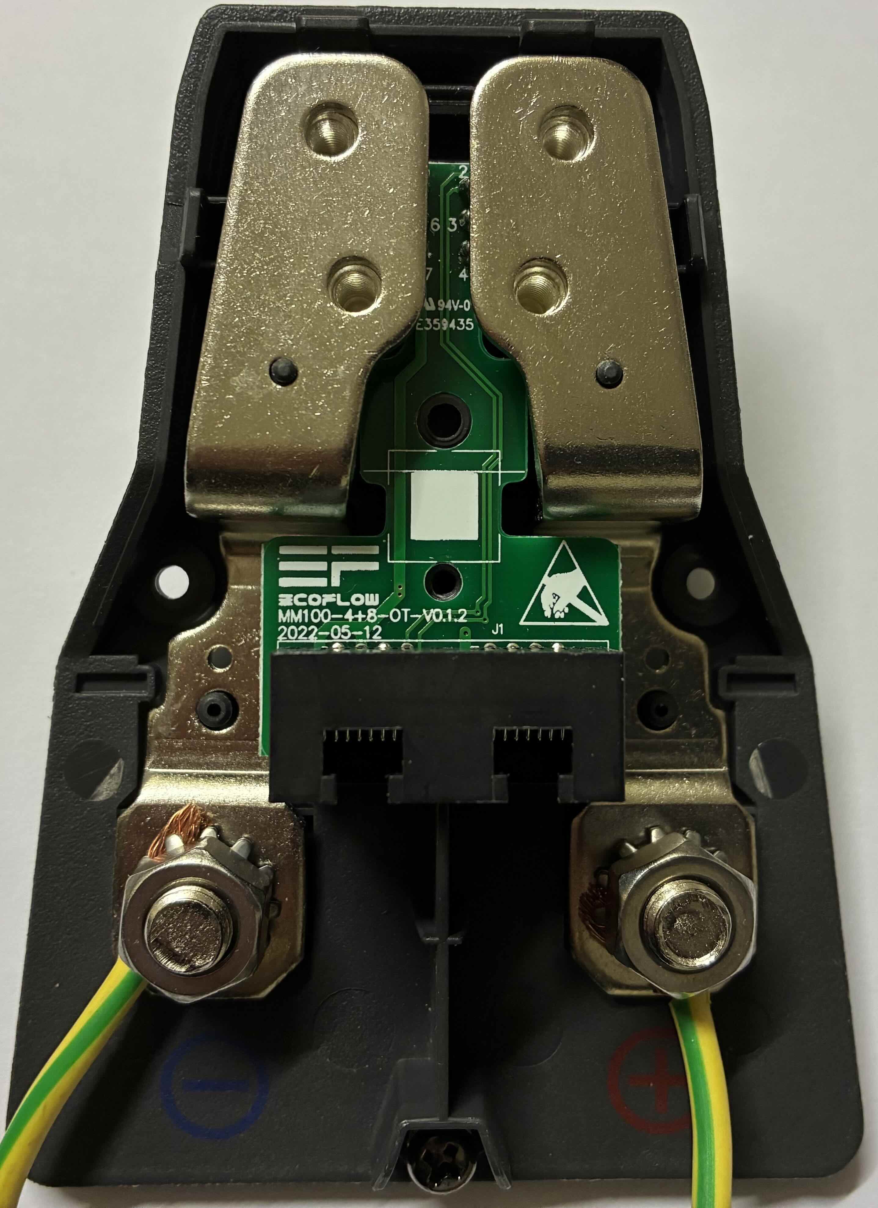
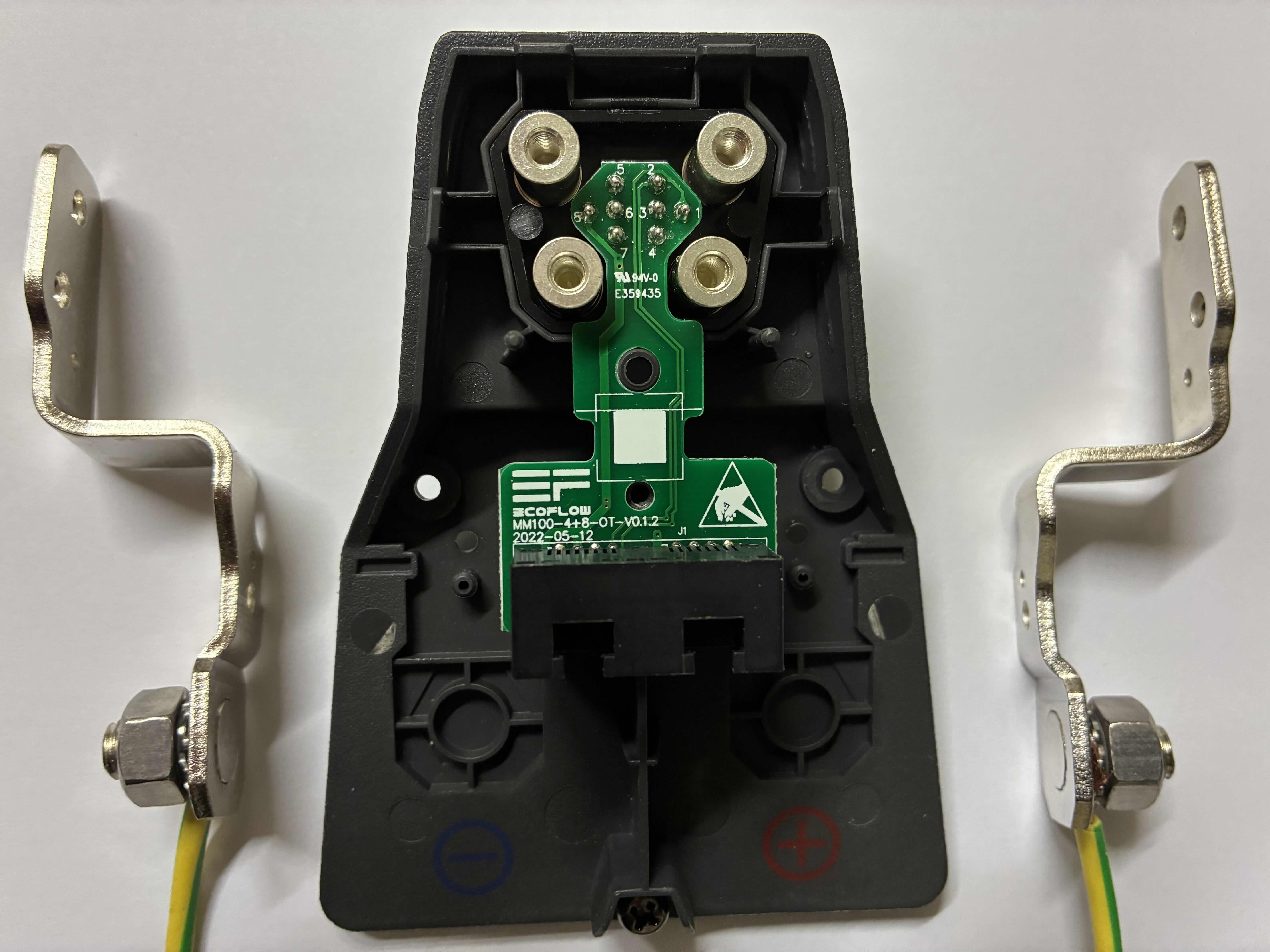
Internal Photos & Assembly
The adapter is held together by screws on the underside of the housing.
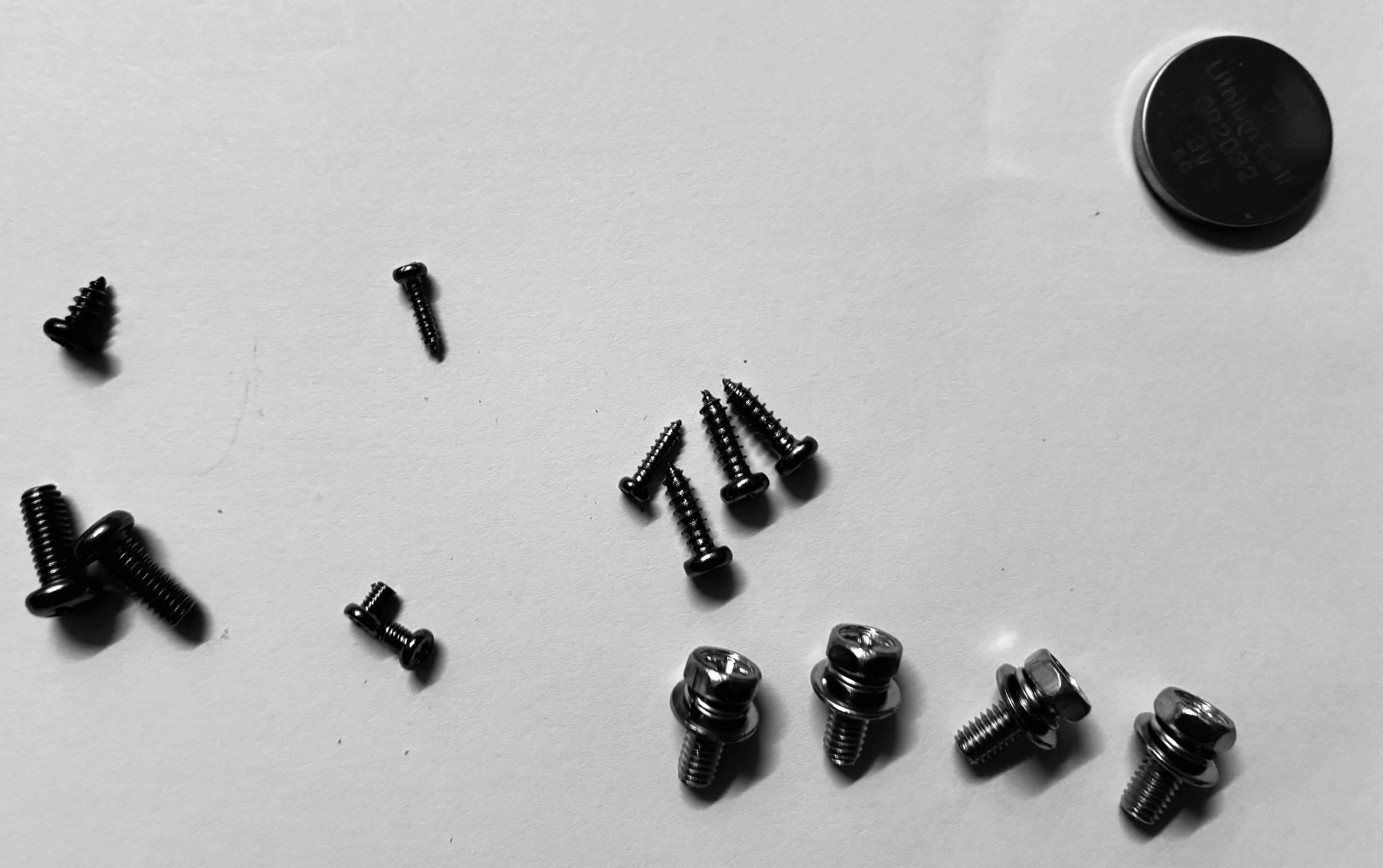 The housing uses several screws.
💡 DIY Implementation
If you don’t have the official adapter, you can use a custom jumper on the 8-pin connector (Shorting 4 and 5) to wake up the battery for use with generic 48V systems.
Voltage Check: With pins 4 and 5 shorted, verify the voltage on the main terminals:
- Nominal: ~51.2V (LFP 16S)
- Full Charge: ~58.4V
🛠 Hardware Tips for DIY Cables
- Power Connectors: Observations show that the high-power terminals inside the proprietary battery port are physically compatible with standard MC4 (Solar) connector pins.
- Compatibility: The larger internal sockets in the terminal appear to match the metal inserts used in MC4 connectors.
[!CAUTION] CURRENT LIMITATIONS: While MC4 pins may fit physically, the original EcoFlow adapter terminals are designed for significantly higher currents (often 50A-80A continuous). Standard MC4 pins are typically rated for 20A-30A.
If you use MC4 pins for a DIY cable:
- Monitor temperatures closely during high-load charging/discharging.
- Understand the power limits of your specific connector.
- Risk of melting: Drawing 80A through a 30A-rated pin will lead to overheating, melting of the connector, and potential fire.
Only use this method for low-power applications or under strictly controlled conditions.